kings technics Pure Sine Wave Inverter Using Arduino
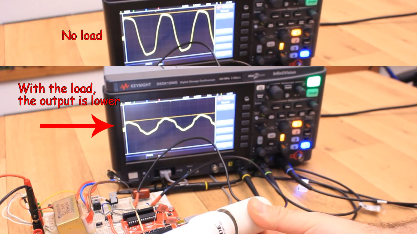
In the Matlab simulation, the inverter can change the 12 vdc to 12 vpeak with a carrier signal of 20 khz and a reference signal of 50 hz. From the results of the inverter output will be changed to 220 vac using a step up transformer. The research overlay is being able to make a pure sine wave SPWM inverter using an ESP32 driver with a stable.
Variable frequency inverter with Arduino circuit
Hi folks and welcome on AT Lab, in this video I'll show you how it works and how to wire a three phase inverter SPWM controlled by an Arduino Nano. A variabl.
Pure Sine Wave Inverter Circuit Using Arduino
In our case we used the Arduino microcontroller ATmega2560 to produce the six SPWM signals by varying the duty cycles of PWM according to a sine lookup table whose frequency " \(f_{r}=50\,{\text {Hz}}\) " is the intended frequency of sinusoidal signal obtained at the output of the inverter. Generally, SPWM is generated for one half cycle.
Arduino Uno SPWM Inverter • Yopie DIY

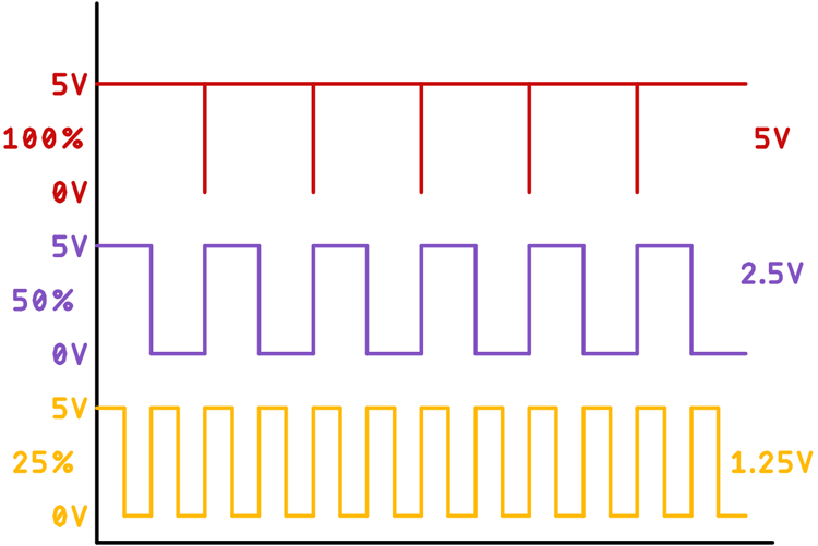
S0, how can we create this SPWM signal? Well, with the Arduino, in the code, we make two pins to be PWM pins by setting some registers, TCCR1B and TCCR1A. Now e have to change the width of this signal by changing the value of the OCR1A.. Arduino SPWM Inverter code (01/12/2019) #include
Arduino SPWM inverter MOSFET dual phase homemade
In this work, a cost-effective sine pulse-width modulation (SPWM) control of an inverter has been implemented using Arduino UNO microcontroller, which can be used with various power stages. The proposed model is focused on power electronics training or learning. It allows users to practice the control of an inverter without the need to be in a face-to-face laboratory. The proposed model.
Spwm Inverter Onda Seno Code Arduino Power Inverter Areas Of

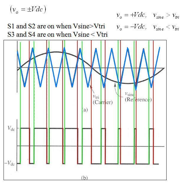
The modulation signal of SPWM is a sinusoidal waveform with a frequency equal to the desired output voltage frequency (50 or 60 Hz). In Figure 3, a simplified schematic of sinusoidal modulation is shown. The switching signal is generated by comparing the sinusoidal waveform and the triangular carrier waveform.
single phase pure sine wave inverter using arduino
In this work, a cost-effective sine pulse-width modulation (SPWM) control of an inverter has been implemented using Arduino UNO microcontroller, which can be used with various power stages. The proposed model is focused on power electronics training or learning.
Three phase inverter PWM coding using SinePWM Arduino + Proteus YouTube

Nearby homes similar to 287 Dushane Dr have recently sold between $210K to $286K at an average of $180 per square foot. SOLD DEC 28, 2023. $277,000 Last Sold Price. 3 beds. 1.5 baths. 1,508 sq ft. 175 Grimsby Rd W, Tonawanda-Town, NY 14223. Listing by HUNT Real Estate ERA, (716) 834-5400. SOLD DEC 4, 2023.
Arduino SPWM inverter MOSFET dual phase homemade
Three phase sine wave inverter is designed using Arduino microcontroller. Arduino is used to generate SPWM singals to drive gate driver circuits as shown in figure below. These SPWM signal are 120 degree out of phase with each other. If you don't know who to generate sinusoidal pulse width modulation signal, I recommend you read my article on.
Single Phase Pure Sine Wave Inverter Using Arduino Riset

Arduino-Atmel-sPWM Implementation of an sPWM signal on Ardunio and Atmel micros Introduction The aim of this repo is to help the hobbyist or student make rapid progress in implementing an sPWM signal on a arduino or atmel micro, while making sure that the theory behind the sPWM and the code itself is understood. Please also note that:
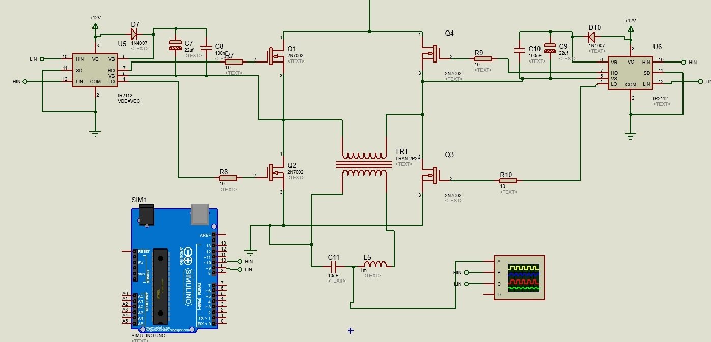
This article explains a simple pure sine wave inverter circuit using

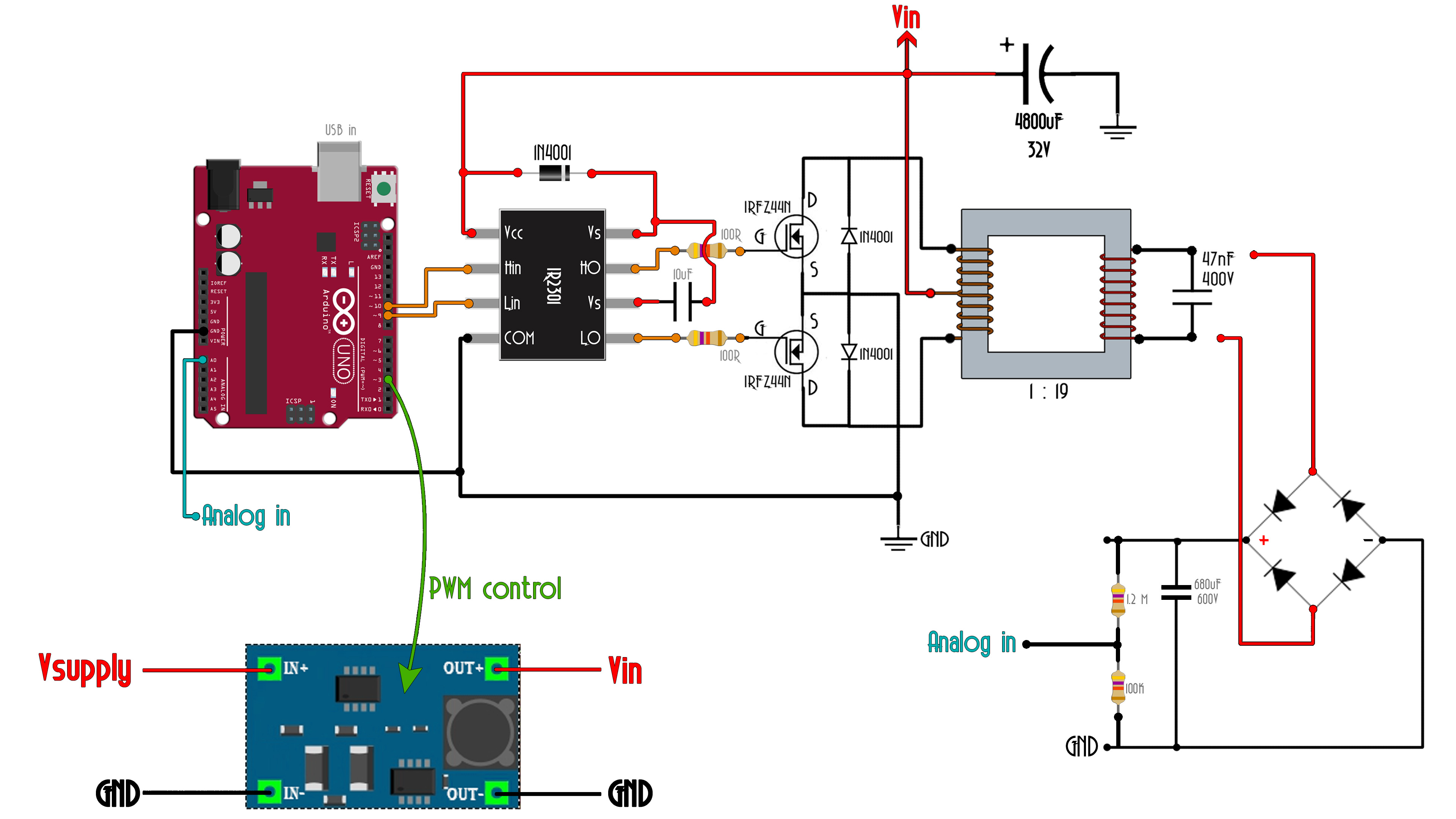
Arduino: Arduino Uno R3 is used to generate control signals for MOSFET driver using SPWM ( sinusoidal pulse width modulation technique). For more information on this technique, you can check my article on pure sine wave inverter using pic microcontroller.
Arduino SPWM inverter Module with Button for On/Off and Save Parameters

What is SPWM (Sinusoidal Pulse Width Modulation)? As the name suggests, SPWM stands for S inusoidal P ulse W idth M odulation. As you may already know, a PWM signal is a signal in which we can change the frequency of the pulse as well as the on-time and off-time, which is also known as the duty cycle.
Arduino pure sinus
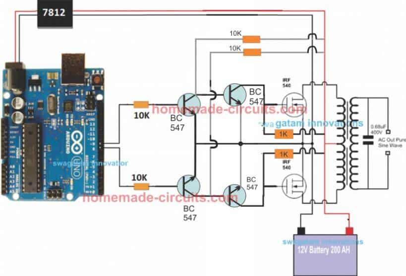
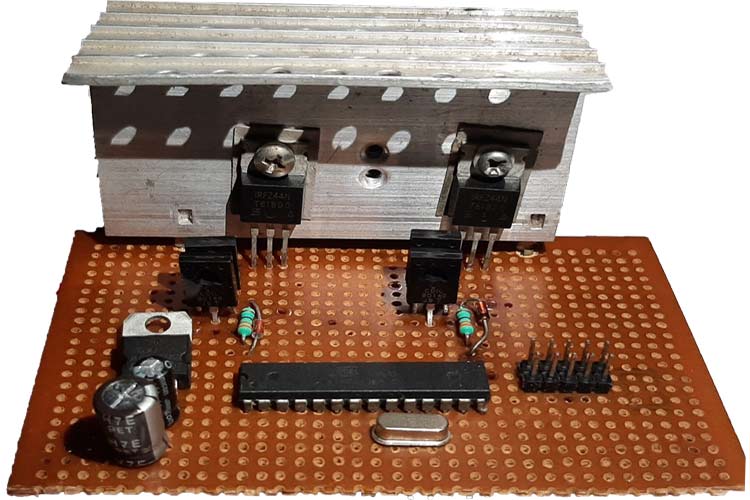
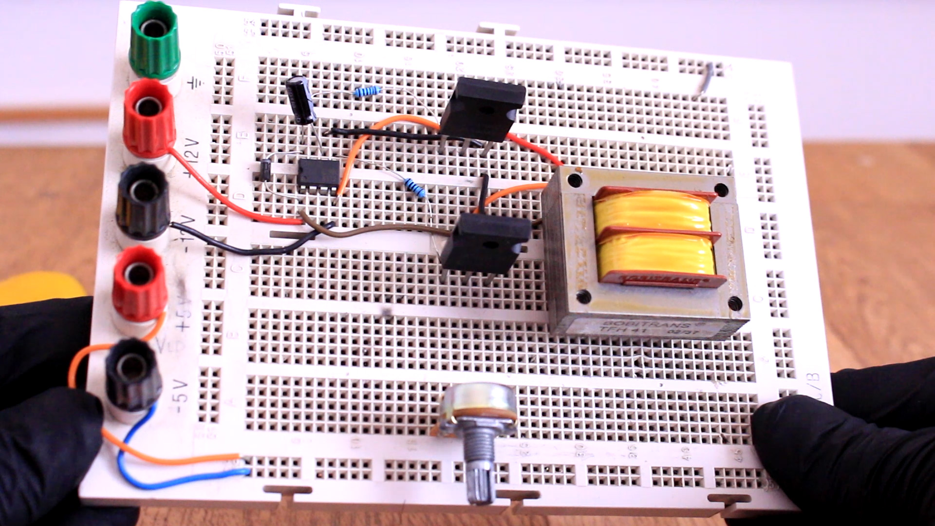
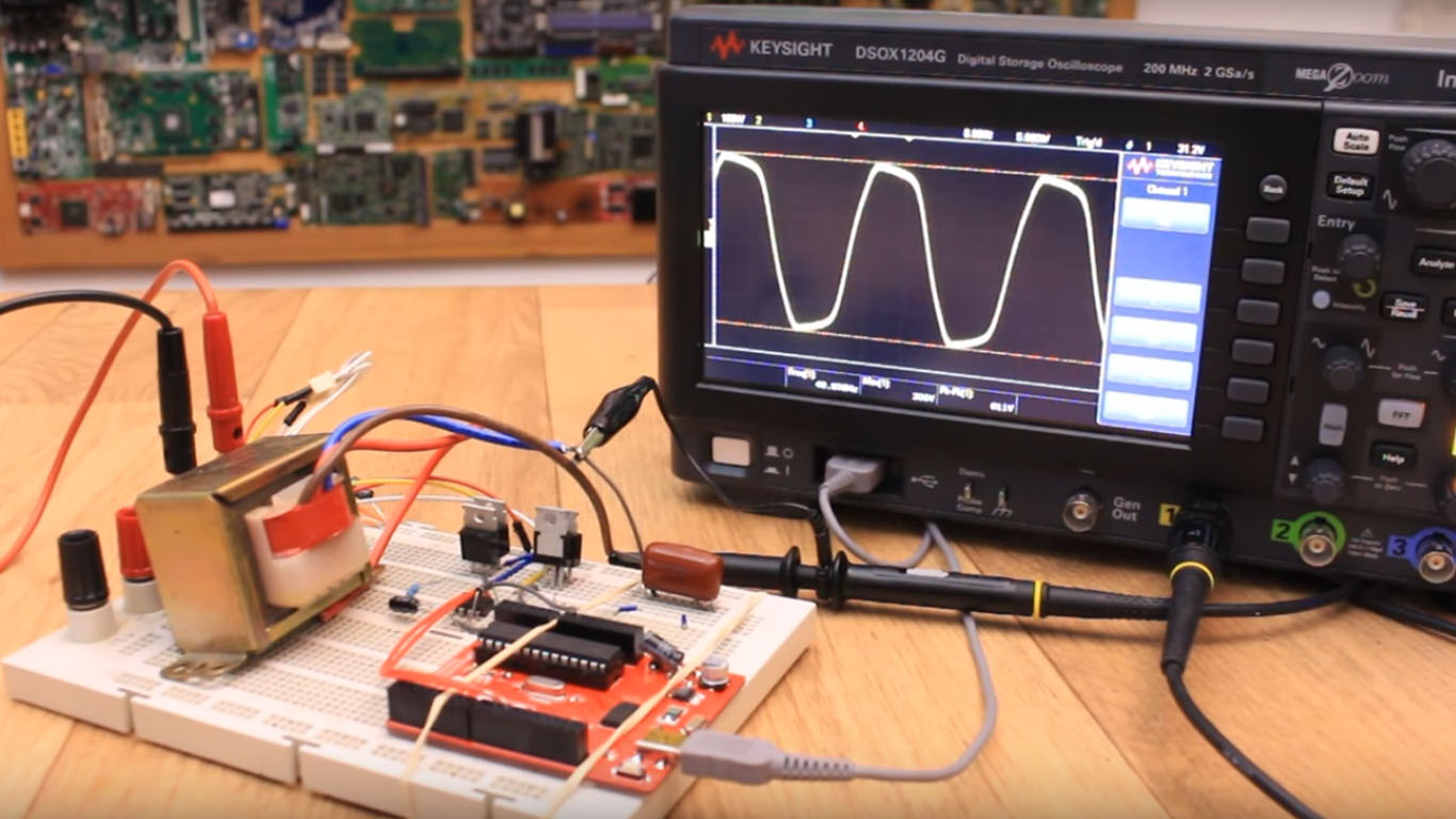
For the full Program Code please visit the following link: Arduino SPWM Generator Circuit Video Clip Parts List All resistors are 1/4 watt, 5% CFR 10K = 4 1K = 2 BC547 = 4nos Mosfets IRF540 = 2nos Arduino UNO = 1 Transformer = 9--9V/220V/120V current as per requirement. Battery = 12V, Ah value as per requirement Delay Effect
SPWM sine INVERTER with Arduino YouTube

Basically, SPWM which stands for sine wave pulse width modulation, is a type of pulse modulation where the pulses are modulated to simulate a sinusoidal waveform, so that the modulation is able to attain properties of a pure sine wave.
Arduino SPWM inverter with full sine output 220V AC tutorial
$2 for 10PCBs (Not only for New User): https://jlcpcb.comThis is just an example of how you could use SPWM to get decent shape sine wave. It is not professio.
Inverter SPWM and Carrier generating using Arduino Mega Forum for
Hi folks and welcome on AT Lab, in this video I'll show you how it works and how to build a three phase inverter SPWM controlled by an STM32. A variable freq.