
How Does A Hydraulic System Work? MCH Hydraulics

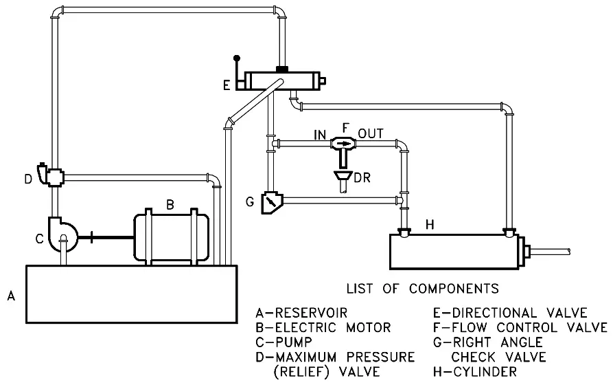
The second is to ask for a circuit diagram for the hydraulic system. Figure 1. Graphical Circuit Diagram. There are four types of hydraulic-circuit diagrams: block, cutaway, pictorial and graphical.. In the case of a mass-produced machine, the hydraulic circuit diagram should be available from the equipment manufacturer on request. If the.
Schematic of the hydraulic system a) machine 1 b) machine 2. Download

Hydraulics engineers regularly encounter these diagrams, but these symbols can be daunting to interpret if you have limited experience with schematics and the fluid power industry. On this page, Carr Lane ROEMHELD provides a comprehensive table outlining the definitions of each symbol used in a hydraulic diagram.
what is hydraulic system Christopher Paige

Fluid Power Diagrams and Schematics Different symbology is used when dealing with systems that operate with fluid power. Fluid power includes either gas (such as air) or hydraulic (such as water or oil) motive media. Some of the symbols used in fluid power systems are the same or similar to those already discussed, but many are entirely different.
Hydraulics mechanical system vector illustration diagram Engineering

Types of Hydraulic Systems (With Diagram) | Fluid Mechanics Article shared by: The following points highlight the eight main types of hydraulic systems. The types are: 1. The Hydraulic Accumulator 2. The Differential Hydraulic Accumulator 3. The Hydraulic Intensifier 4. The Hydraulic Ram 5. The Hydraulic Lift 6. The Hydraulic Crane 7.
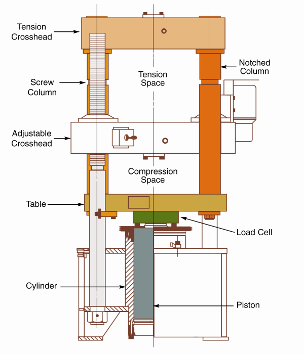
Do I retrofit or replace my hydraulic universal testing machine?
by Chris Woodford. Last updated: November 19, 2021. What's the connection between a water pistol and this gigantic crane? On the face of it, no connection at all. But think about the science behind them and you'll reach a surprising conclusion: water pistols and cranes use the power of moving liquids in a very similar way.
Schematic diagram of the hydraulic press. volume flow rate and matching

And so is an accurate diagram. It can also be worth a lot of nickel. Consider the four main types of hydraulic diagrams in common use — and the consequences of having to manage a hydraulic machine without them: Block Diagrams show the components of a hydraulic circuit as blocks joined by lines, which indicate connections and/or interactions.
Hydraulic Circuit Diagram Ppt

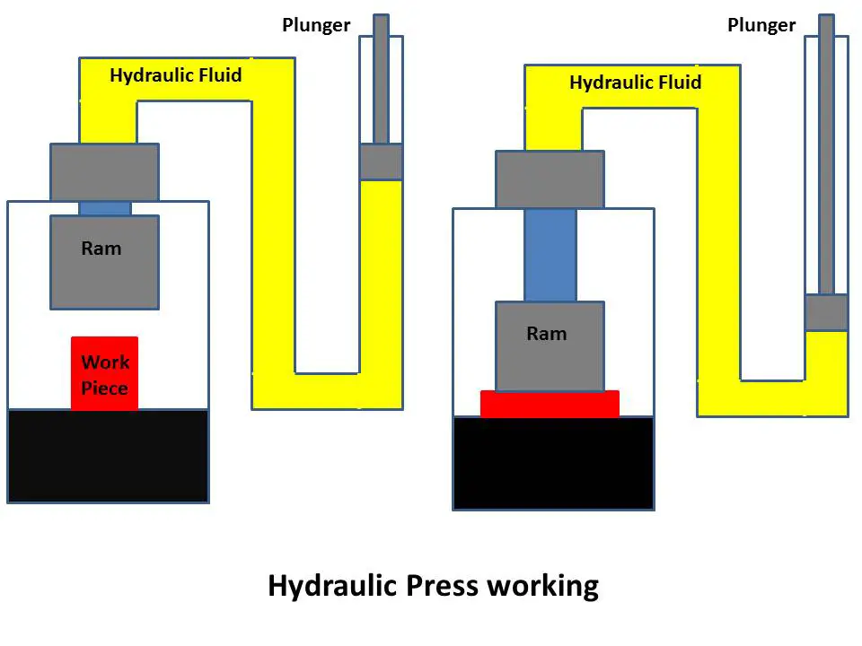
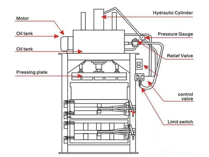
Hydraulic Press: Diagram, Working, Types & Application [PDF] Last Updated on: March 1, 2023 by Yousef In this article, you will learn what is Hydraulic Press? Its working, parts, advantages, disadvantages, applications, and types of hydraulic press are explained with diagrams.
How To Read A Hydraulic Schematic Diagram Wiring Diagram
The hydraulic press machine (also referred to as a hydraulic oil press) utilizes the static pressure of a liquid to process materials such as metal, plastic, rubber, wood, and powdered products.
Hydraulic Press Principle, Construction, Working with Applications
Hydraulic Machines are machinery and tools that use fluid power for its functioning. In these machines, a large amount of power is transferred through small tubes and hoses.
Schematic diagram of hydraulic motor system. Download Scientific Diagram

First things first - identify the symbols. Hydraulic schematics use a wide range of symbols to represent different parts and connections. Familiarize yourself with these symbols by consulting books or manuals that describe what each symbol stands for. This will make it much easier to interpret the schematic. Next, pay attention to the arrows.
Hydraulic Circuit Diagram Animation
In order to check the function of a hydraulic machine we need a diagram. Consequently there are various type of drawings, one of which I want to discuss in this section is the hydraulic diagram. For the purpose to make a hydraulic circuit understandable, each element in the installation is represent by a specific symbol.
How to read Hydraulic Schematic Diagram YouTube

A hydraulic press is a machine press that generates compressive force by the use of a hydraulic cylinder. It is a device that is used for lifting heavyweights with the application of a much smaller force. The hydraulic press was invented by Joseph Bramah in England. He accomplished the project in the 17 th century (1795).
HYDRAULIC SYSTEM FOR BEGINNERS Mechanical Engineering Professionals

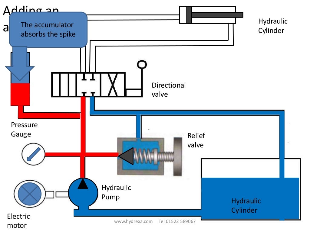
1. Reservoir / Oil Tank. They are used to hold the hydraulic oil. 2. Hydraulic Pump. They are used to pressurized the hydraulic fluid and force the fluid through the system.There are three types of hydraulic pump: I. Fixed Displacement Pump - These pump has a set flow rate means every stroke of the motor moves same amount of fluid.
Aircraft systems Basic Hydraulic Systems

A hydraulic circuit is a system comprising an interconnected set of discrete components that transport liquid.
The hydraulic circuit diagram of a plant with two actuators. Download

Basic Diagrams and Systems In the preceding chapters, you learned about hydraulic and pneumatic fluids and components of fluid power systems. While having knowledge of system components is essential, it is difficult to understand the interrelationships of these components by simply watching the system operate.
simple hydraulic circuit drawing Wiring Diagram and Schematics
1. Identifying the line types In a hydraulic schematic, each line type has a unique meaning. In addition, colors can be added to indicate purpose of the line. In the figure below, all of the basic line types are shown. The basic line is a solid line that represents a working pressure hose or tube.