audio stereo circuit Page 5 Audio Circuits Next.gr
Quick facts BA5417 Power output: 5W + 5W into 3 ohms at 10% 1kHz distortion with power supply 12V Power output: 6W + 6W into 4 ohms at 10% 1kHz distortion with power supply 15V Power output: 3.5W + 3.5W into 8 ohms at 10% 1kHz distortion with power supply 15V Power output: 2W + 2W into 8 ohms at 10% 1kHz distortion with power supply 12V
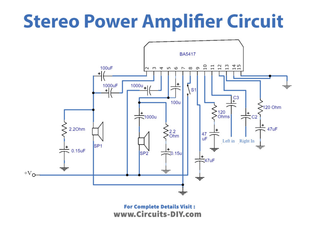
2×5 W Stereo Power Amplifier Circuit based on BA5417
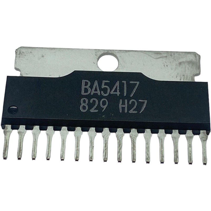
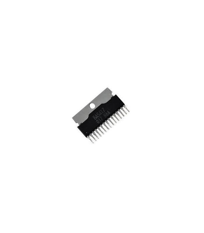
BA5417 Product details. The UTC BA5417 is a dual power amplifier of 6~15V-compatible for radio cassette/Mini compo players use. It is developed to equip with standby switching functions for excellent total harmonic distortion and other basic characteristics. * Operating power supply voltage range from 6V to 15V. * High output.
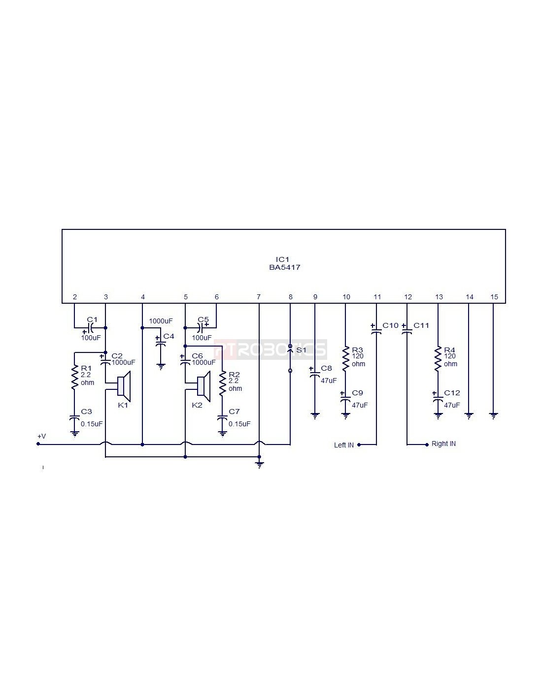
Ba5417 Circuit Diagram

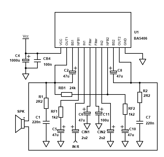
Description The BA5406 / BA5417 is a dual OTL monolithic power IC with two built-in, high output speaker amplifier circuits. High output of 5W×2 can be produced when VCC=12 V and RL=3Ω, and 2.8 W×2 when VCC=9V and RL=3Ω. The BA5406, which uses a high allowable power dissipation package, has a simple heatsink design.
Ba5417 Amplifier Circuit Diagram Instructions Anya Circuit

The BA5406/BA5417 is a dual OTL monolithic power IC with two built-in, high output speaker amplifier circuits. High output of 5W×2 can be produced when VCC=12 V and RL=3Ω, and 2.8 W×2 when VCC=9V and RL=3Ω. The BA5406, which uses a high allowable power dissipation package, has a simple heatsink design.
BA5417 stereo power amplifier schematic circuit diagram

The BA5406/BA5417 is a dual OTL monolithic power IC with two built-in, high output speaker amplifier circuits. High output of 5W×2 can be produced when VCC=12 V and RL=3Ω, and 2.8 W×2 when VCC=9V and RL=3Ω. The BA5406, which uses a high allowable power dissipation package, has a simple heatsink design.
BA5417 Integrated Circuit
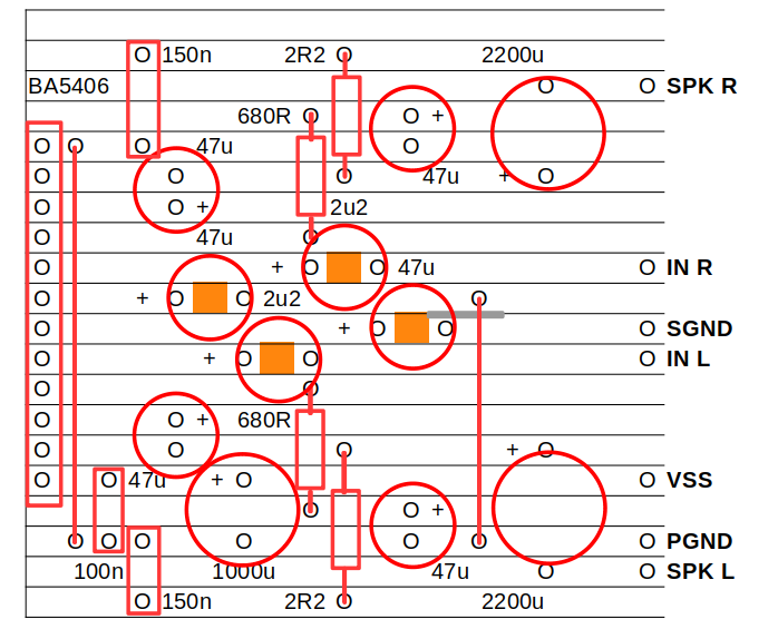
Circuit Diagram PCB layout TOP SILKSCREEN - BOTTOM VIEW BOTTOM LAYER - TOP VIEW Usage 1 Please set the switches STBY (Standby mode). 2 Connect Power supply, Speaker, and Audio Source. 3 Set Power supply 9V(Typ.). 4 Set the switches in order of STBY → NORMAL(Sound output mode) 5 Confirm the sound.
BA5417 Stereo power amplifier
Tech Specs Images Price and Stock Powered by BA5417 Datasheet Technical Specifications ROHM BA5417 technical specifications, attributes, and parameters. Audio Amp Speaker 2-CH Stereo 5W Class-AB 15-Pin (15+Tab) HSIP Tube. BA5417 Series 6 - 15 V 5W x 2 Stereo Speaker Amplifier w/ HSIP-15. Audio Power Amplifier, -20 C, Sip, 75 C Rohs Compliant: Yes.
BA5417, BA5406 DIY Guide 5W Stereo Single Chip Power Amp
The BA5406/BA5417 is a d ual OTL monolithic power IC with two bu ilt-in, high output speaker amplifier circuits. High output of 5W×2 can be produced when V CC=12 V and RL=3Ω, and 2.8 W×2 when VCC=9V and RL=3Ω. The BA5406, which uses a high allowable po wer dissipation package, has a simple heatsink design.
BA5417, BA5406 DIY Guide 5W Stereo Single Chip Power Amp
ROHM Semiconductor is a Japanese semiconductor company that was founded in 1958. The company specializes in the design and manufacture of a wide range of products including power management, power devices, and analog and mixed-signal integrated circuits. ROHM's products are used in various applications such as consumer electronics, automotive.
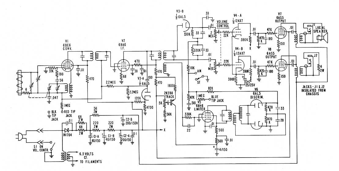
6W amplifier using TA7222AP Electronic Circuits and Diagrams
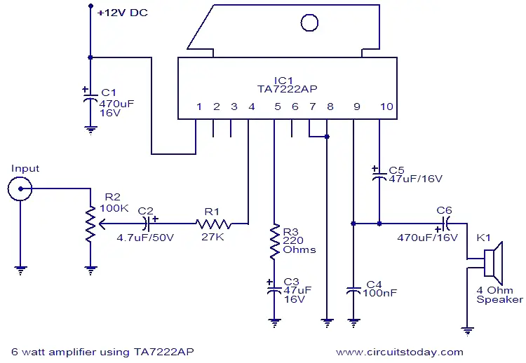
Fig. 1: Logical operators and fault-tolerant operations of the Iceberg code. Fig. 2: Comparing the performance of a random mirror circuit encoded with the Iceberg code against the unencoded.
Elsie Circuit Ba5417 Amplifier Circuit Diagram Pictures

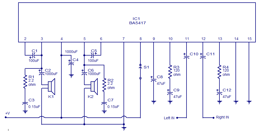
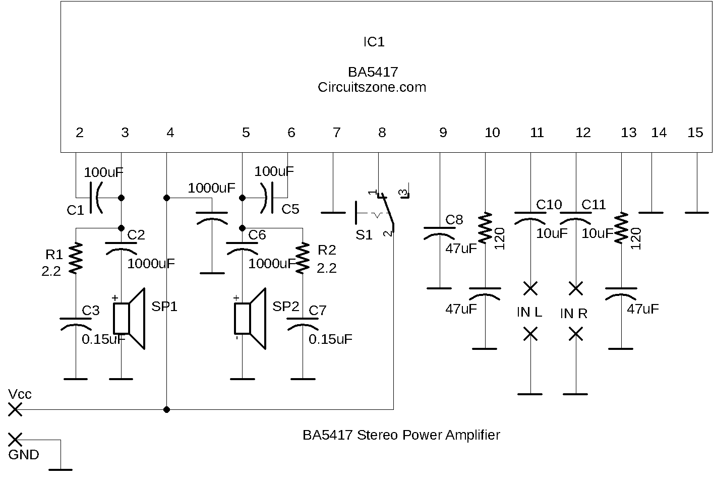
Circuit diagram. BA5417 stereo amplifier circuit Notes. Supply voltage range of BA5417 is from 6 to 15V DC. The recommended supply voltage for this circuit is 12V DC. The power supply must be well regulated and filtered. BA5417 requires a heatsink. The circuit can be assembled on a perf board without much degradation in performance.
5x2 wattt stereo amplifier circuit using BA5417. Operates from 12V DC
BA5417 is Obsolete and no longer manufactured. Available Substitutes: Similar DRV601RTJR Texas Instruments In Stock: 41,315 Unit Price: $1.54000 Datasheet Similar INA2134UA/2K5 Texas Instruments In Stock: 7,283 Unit Price: $4.20000 Datasheet Similar INA2137PA Rochester Electronics, LLC In Stock: 12,759 Unit Price: $2.68000 Datasheet Similar LM4880M
BA5417 de OEM Circuito integrado BA5417
BA5406,BA5417 h Description The BA5406/BA5417 is a dual OTL monolithic power IC with two bu ilt-in, high output speaker am plifier circuits. High output of 5W×2 can be produced when V CC =12 V and R L =3 , and 2.8 W×2 when V CC =9V and R L =3 . The BA5406, which uses a high allowable power dissipation package, has a simple heatsink design.
Elsie Circuit Ba5417 Amplifier Circuit Diagram Chart

Circuit diagram Notes The supply voltage range of BA5417 is from 6 to 15V DC. The recommended supply voltage for this circuit is 12V DC. The power supply must be well regulated and filtered. BA5417 requires a heatsink. The circuit can be assembled on a perf board without much degradation in performance.
Stereo Power Amplifier Circuit Based BA5417 IC »
Class-AB monaural speaker amplifiers designed for automotive applications. AEC-Q100 Qualified Sound Processor IC designed for high-quality automotive audio applications. AEC-Q100 qualified audio processor ICs geared towards car audio applications. Variety of Audio ICs ideal for a wide range of applications.
BA5417 ROHM Amplifier ICs Jotrin Electronics

1 Introduction to Power Amplifier 2 Hardware Components 3 BA5417 Pinout 4 Power Amplifier Circuit 5 Working Explanation 6 Application and Uses Introduction to Power Amplifier A circuit that increases the level of its input power to drive the different loads is known as the Power Amplifier Circuit.